Assembly
CANarchy is deliverd as a DIY kit that you need to solder yourself. It includes all the necessary parts to get you started.
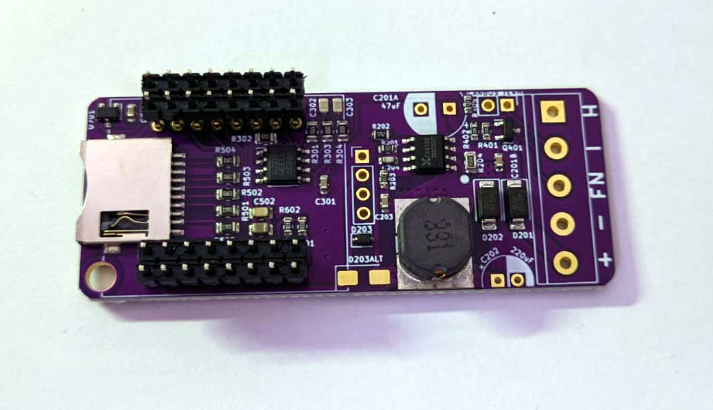
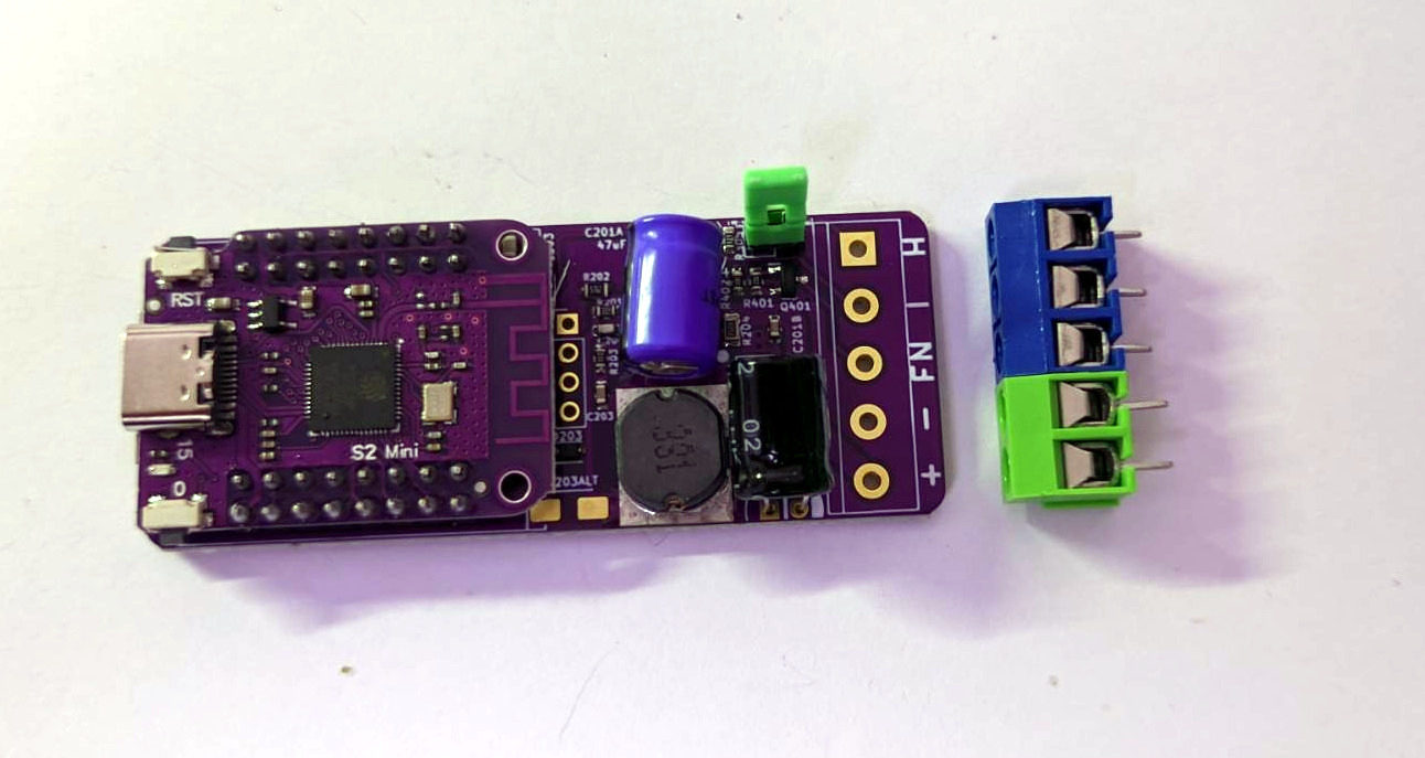
All the parts
- There are
2 Trough hole Capacitors
1 Screwterminal with 2 connectors
1 Screwterminal with 3 connectors
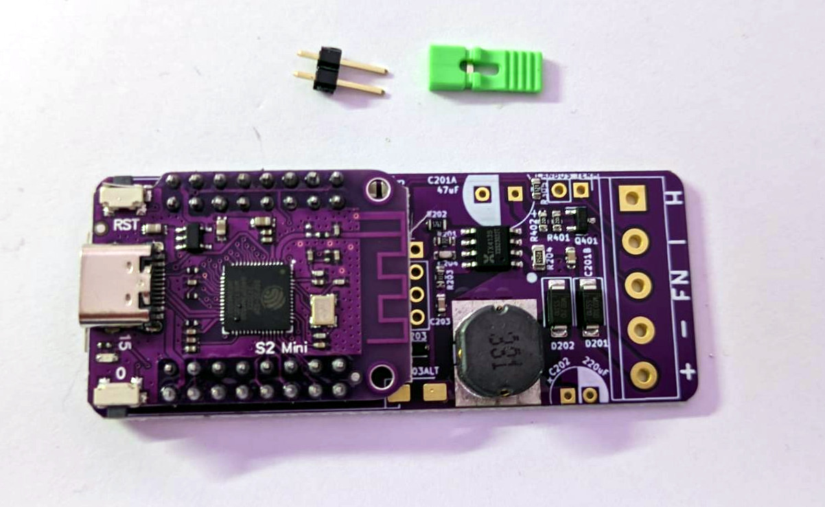
1 Jumper
1 OLED Display
1 Microcontroller board based on ESP32-S2 (preflashed)
Some pinheaders

The MCU
Start with Soldering the Microcontroller, The USB connector faces outward. Canarchy is built around the ESP32-S2, a very powerful microncontroller running circuitpython. It has 8 MB of flash and 2MB of RAM. Thats a LOT.
Pinheaders, long leads go in the PCB
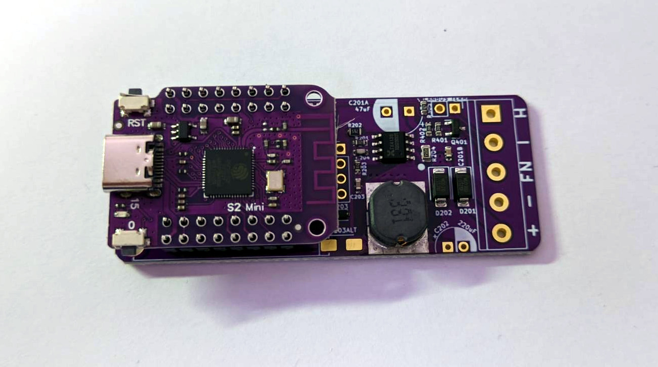
Microcontroller on top
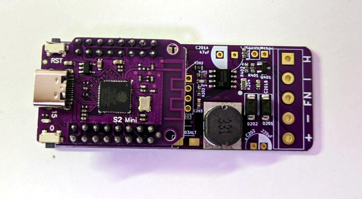
Solder all pins, make sure they are not connected to each other
Solder all the pins on the bottom side of the PCB. Ensure the MCU sits as flat as possible. Clip off all the Leads when done.
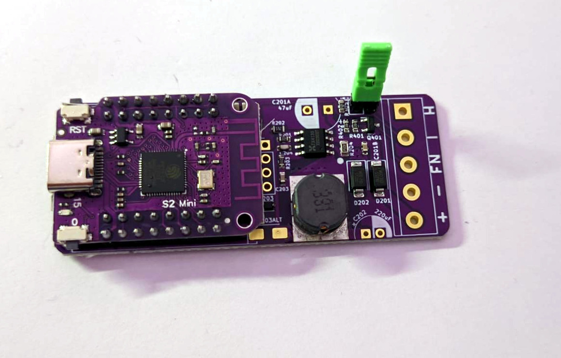
The Jumper
Now solder the Jumper in place. The Jumper is needed for CANbus termination and should be removed in scenarios where you are only listening to traffic without being an actual endpoint. If you don’t see data on the CANbus, but there should be data, try to remove the jumper.
Capacitors
Next up are the Capacitors, bend the leads as shown.
They should sit as flat as possible. The orientation is super important! They DO have a polarity and soldering them in the wrong way, will make them pop and release the magic smoke, rendering them useless.
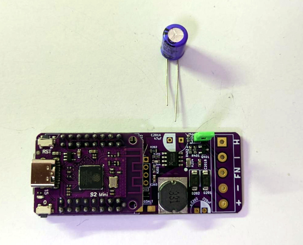
Capacitor 47 uF, bent the leads as shown
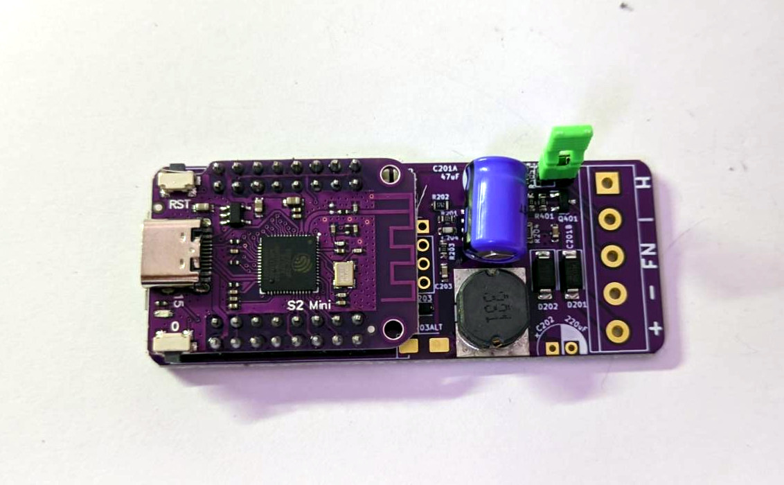
Place as shown, the BLACK mark (-) points to the USB conector
Doubleck that the shorter lead is on the side of the MCU before soldering
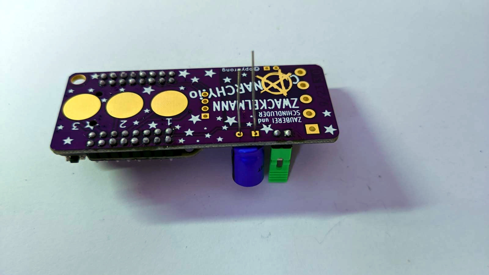
Next up is the 220uF Capacitor on the bottom. The polarity here is exactly the other way around, so make sure to get that right.

Capacitor 220 uF Ground is on the side of the screw terminals.

Insert as shown
This is how your board should look now with both caps in place.
Screwterminals
Now solder the screwterminals. They may come in different colors, but thats not important. Make sure to connect/ stack them together before soldering.

Display
And finally the OLED Display. It should come with a tape on the bottom so it does not touch the pins of the MCU. You can remove the foil to make it stick before soldering. The spacing is very tight, you might have to apply a little pressure to the display to get them pins to stick trough the PCB.

You are done with assembly! Connect your board to a USB-C cable. It should blink the onboard blue LED of the MCU 3 times and show you the canarchy boot logo. Go get yourself a cup of tea (or whatever it is you do to reward yourself)

A schematic and sourcefiles are available on gitlab